It will cause area 1 to not receive any inter-area routes and will use a default route to reach networks in other areas.
To define an area as a stub area, use the area stub command in router configuration mode. To disable this function, use the no form of this command.
area area-id stub [no-summary] no area area-id stub no area area-id
area-id = Identifier for the stub area; either a decimal value or an IP address.
no-summary = (Optional) Prevents an ABR from sending summary link advertisements into the stub area.
Defaults: No stub area is defined.
Command Modes: Router configuration
You must configure the area stub command on all routers and access servers in the stub area. Use the area router configuration command with the default-cost option to specify the cost of a default internal router sent into a stub area by an area border router.
There are two stub area router configuration commands: the stub and default-cost options of the area router configuration command. In all routers attached to the stub area, the area should be configured as a stub area using the stub option of the area command. Use the default-cost option only on an ABR attached to the stub area. The default-cost option provides the metric for the summary default route generated by the area border router into the stub area.
To further reduce the number of link state advertisements (LSAs) sent into a stub area, you can configure no-summary on the ABR to prevent it from sending summary LSAs (LSA type 3) into the stub area.
Cisco IP NGN Architecture
The Cisco IP NGN is a next-generation service provider infrastructure for video, mobile, and cloud or managed services.
It provides an all-IP network for services and applications, regardless of access type.
Application Layer: Mobile Access, Residential Access, Business Access
Services Layer: Mobile Services, Video Services, Cloud Services
IP Infrastructure Layer: Access, Aggregation, IP Edge, Core
Cisco IP NGN Infrastructure Layer
Routing protocols used in service provider environments focus on the IP infrastructure layer of the Cisco IP NGN.
Routing protocols used in service provider environments focus on service provider core and edge devices and customer devices.
Overview of Routing Protocols
High-level objective:
Provide connectivity to the Internet for end customers and subordinate ISPs
Optionally, provide transit connectivity between service providers (that are Tier 1 ISPs)
Support additional features required in MPLS-enabled networks
On Cisco IOS XR Software, set of commands is used to enable the gi0/0/0/1 interface for OSPF in area 0 are:
router ospf 1
area 0
interface GigabitEthernet0/0/0/1
The OSPF router ID:
The OSPF routing process chooses a router ID for itself when it starts up.
The router-id command is the preferred procedure to set the router ID.
After the router ID is set, it does not change, even if the interface
that the router is using for the router ID goes down. The router ID
changes only if the router reloads or if the OSPF routing process
restarts.
OSPF network scenarios require OSPF virtual link configuration:
to connect an OSPF non-backbone area to area 0 through another non-backbone area.
to connect two parts of a partitioned backbone area through a non-backbone area.
Routing Example
Part 1: BGP
1. R1 receives an external BGP update: 209.165.201.0/24; next hop is 192.168.200.2.
2. R4 receives an internal BGP update:
- By default, next-hop address does not change.
- Optionally, BGP on R1 can be configured to change the next-hop address to its own address (typically a loopback address).
3. R4 forwards the update and changes the next-hop address to 192.168.11.1
Part 2: IGP
R1 propagates the BGP next-hop address to all routers in the domain:
- Edge subnet (192.168.200.0/30) for reachability of external BGP next-hop addresses.
- Loopback address (10.1.1.1/32) for reachability of internal BGP neighbors.
R2 and R3 forward the information:
- Unchanged (required if the network also uses MPLS-based services such as MPLS VPNs and Cisco MPLS TE).
- Optionally, summarization can be used within IGP for optimization.
Part 3: Routing Table
End-to-end connectivity is provided thorough recursive routing table lookups (optimized by Cisco Express Forwarding):
- BGP for end prefixes.
- IGP for BGP next-hop reachability.
Overview of OSPF
Link-state protocol: routers aware of network topology.
Hierarchical: dual-layer architecture:
- Backbone area: Area 0
- Nonbackbone areas interconnected through Area 0
Creates a neighbor relationship by exchanging hello packets.
Propagates LSAs rather than routing table updates.
- Link: Router interface.
- State: Description of an interface and its relationship to neighboring routers.
Floods LSAs to all OSPF routers in the area, not just directly connected routers.
Pieces together all the LSAs generated by the OSPF routers to create the OSPF link-state database.
Uses the SPF algorithm to calculate the shortest path to each destination and places it in the routing table.
Link-State Data Structure
Neighbor table:
- Also known as the adjacency database.
- Contains list of recognized neighbors.
Topology table:
- Typically referred to as LSDB.
- Contains all routers and their attached links in the area or network.
- Identical LSDB for all routers within an area.
Routing table:
- Commonly named a forwarding database.
- Contains list of best paths to destinations.
Area Terminology and Router Types
ABR: Area Border Router
ASBR: Autonomous System Boundary Router
Regular nonbackbone area
- Area routes
- Summaries
- External routes
Stubby area
- Summaries
Totally stubby area
- Default route only
Not-so-stubby area (NSSA)
- Summaries
- External routes
Totally NSSA
- Default route
- External routes
OSPF Metric
Each link is assigned a cost:
- Default cost calculated from interface bandwidth
- Default reference bandwidth is 100 Mb/s
- Modify reference bandwidth in 1 Gb/s networks
- Cost can be statically configured for an interface
Ensure consistent configuration of costs:
- Same cost on both sides of a link when manually configuring the cost
- Same reference bandwidth on all routers in an OSPF domain
Cost = Reference Bandwidth / Interface Bandwidth
Typical OSPF Designs
Single-area design:
- All routers in Area 0
- Simple routing design
- Mostly point-to-point adjacencies
- Optimal routing decisions
- Scalability limited to a few hundred routers in the network
Multi-area design:
- Regular areas or NSSA typically used
- Scales to thousands of routers in the network
- Mostly point-to-point adjacencies
- More complex routing design
- May result in suboptimal routing (for example, dual attached areas)
- Less practical in MPLS-enabled networks
Overview of IS-IS
Stable protocol
Originally deployed by ISPs because U.S. government mandated Internet support of OSI and IP
IS = router
IS-IS was originally designed as the IGP for the Connectionless Network Service (CLNS), part of the OSI protocol suite.
The OSI protocol suite Layer 3 protocol is the Connectionless Network Protocol (CLNP).
IS-IS uses CLNS addresses to identify routers and build the LSDB.
Hierarchical Design
Hierarchical: dual-layer architecture:
- Level 1 used within local areas
- Level 2 interconnects areas
IS-IS Characteristics
Link-state routing protocol (routers aware of network topology)
Supports VLSMs
Uses Dijkstra SPF algorithm, has fast convergence
Uses hellos to establish adjacencies and LSPs to exchange link-state information
Efficient use of bandwidth, memory, and processor
Supports two routing levels:
- Level 1: Builds common topology of system IDs in local area and routes within area using lowest cost path.
- Level 2: Exchanges prefix information (area addresses) between areas. Routes traffic to area using lowest cost path.
Each router has topology information for its area.
IS-IS is part of OSI and was originally used with CLNS only.
IS-IS still uses CLNS to maintain adjacencies and build an SPF tree.
Integrated IS-IS can also carry IP routing information in its updates.
Wide-style metric should be used for large high-speed service provider networks (24-bit link metric, 32-bit path metric).
Link cost defaults to 10.
Each router is identified using a unique NSAP address.
Router and Link Types
Router types:
- Level 1 routers only peer with other Level 1 routers.
- Level 2 routers only peer with other Level 2 routers.
- Levels 1 and 2 routers can peer with any router.
Link types:
- Level 1: Only for Level 1 adjacencies within the same area
- Level 2: Only for Level 2 adjacencies
- Level 1 and Level 2: For Level 1 adjacencies within the same area and Level 2 adjacencies
BGP Overview
BGP is designed for routing information exchange between different administrative domains (autonomous systems).
Each AS is identified using a unique AS number.
BGP is designed with the following major characteristics:
- Scalability: It needs to carry the full Internet routing table (several hundreds of thousands of routes).
- Stability: The size of the routing table results in higher chances of constant flapping of routes.
- Security: Advanced filtering options for protection from other administrative domains.
- Flexibility: Advanced mechanisms in combination with many BGP attributes enable the implementation of complex routing policies.
BGP Architecture
There are two types of BGP sessions:
- External BGP (EBGP) sessions exchange routing information.
- Internal BGP (IBGP) sessions exchange routing information between routers within the same AS.
BGP Characteristics
BGP is a path vector protocol with enhancements:
- Reliable updates
- Triggered updates only
- Rich metrics (called path attributes)
- Designed to scale to huge internetworks
Reliable updates:
- TCP used as transport protocol
- No periodic updates
- Periodic keepalives to verify TCP connectivity
- Triggered updates batched and rate-limited
+ Every 5 seconds for internal peer
+ Every 30 seconds for external peer
BGP was designed to perform well in these areas:
- Interdomain routing applications
- Huge internetworks with large routing tables
- Environments that require complex routing policies
Common BGP uses:
- Customers connected to more than one service provider
- Service provider networks (transit autonomous systems)
- Service provider exchanging traffic at an exchange point (CIX, GIX, NAP, and so on)
- Network cores of large-enterprise customers
RP/0/RSP0/CPU0E1(config-ospf)#distance Cisco IOS-XR command is a function to modify the administrative distance of the OSPF routes.
distance (OSPF)
To define an administrative distance, use the distance command in the appropriate mode. To remove the distance command from the configuration file and restore the system to its default condition in which the software removes a distance definition, use the no form of this command.
weight = Administrative distance. Range is 10 to 255. Used alone, the weight argument specifies a default administrative distance that the software uses when no other specification exists for a routing information source. Routes with a distance of 255 are not installed in the routing table.
ip-address = (Optional) IP address in four-part, dotted-decimal notation.
wildcard-mask = (Optional) Wildcard mask in four-part, dotted decimal format. A bit set to 1 in the mask argument instructs the software to ignore the corresponding bit in the address value.
access-list-name = (Optional) Name of an IP access list to be applied to incoming routing updates.
By default, Level 1 routers within an IS-IS area do not carry any
routing information external to the area to which they belong. They use a
default route to exit the area.
IS-IS supports "route leaking" in which selected Level 2 routes can be advertised by a Level 1/Level 2 router into Level 1.
With IS-IS, an individual router is in only one area, and the border
between areas is on the link that connects two routers that are in
different areas.
Cisco IOS XR Software supports multitopology
for IPv6 IS-IS unless single topology is explicitly configured in IPv6
address-family configuration mode.
Single-Topology IPv6 Support
Single-topology
IPv6 support on Cisco IOS XR software allows IS-IS for IPv6 to be
configured on interface along with an IPv4 network protocol. All
interfaces must be configured with the identical set of network
protocols and all routers in the IS-IS area (for Level 1 routing) or the
domain (for Level 2 routing) must support the identical set of network
layer protocols on all interfaces.
When single-topology support
for IPv6 is used, only narrow link metrics, also known as old-style
type, length, value (TLV) arguments, may be employed. During
single-topology operation, one shortest path first (SPF) computation per
level is used to compute both IPv4 and IPv6 routes. Using a single SPF
is possible because both IPv4 IS-IS and IPv6 IS-IS routing protocols
share a common link topology.
Because multitopology is the
default behavior in the software, you must explicitly configure IPv6 to
use the same topology as IPv4 in order to enable single-topology IPv6. Configure the single-topology command in ipv6 address family configuration submode of the IS-IS router stanza.
Multitopology IPv6 Support
Multitopology IPv6 support on Cisco IOS XR software differs from Cisco IOS Software in that IS-IS assumes that multitopology support is required as soon as it detects interfaces configured for both IPv6 and IPv4 within the IS-IS stanza.
You must use the metric-style wide command to configure IS-IS to wide link metrics as multitopology link advertisements.
When configuring IPv4 and IPv6 IS-IS routing on Cisco IOS XR routers. By default, the IS-IS router type is Level 1 and Level 2, metric-style narrow is used, and the IS-IS interface circuit type is Level 1 and Level 2.
(Optional) Configures the system type (area or backbone router).
By default, every IS-IS instance acts as a level-1-2 router.
The level-1 keyword configures the software to perform Level 1 (intra-area) routing only. Only Level 1 adjacencies are established. The software learns about destination inside its area only. Any packets containing destinations outside the area are sent to the nearest level-1-2 router in the area.
The level-2-only keyword configures the software to perform Level 2 (backbone) routing only and the router establishes only Level 2 adjacencies, either with other Level 2-only routers or with level-1-2 routers.
The level-1-2 keyword configures the software to perform both Level 1 and Level 2 routing. Both Level 1 and Level 2 adjacencies are established. The router acts as a border router between the Level 2 backbone and its Level 1 area.
The default metric style for single topology is narrow metrics. However, you can use either wide metrics or narrow metrics. How to configure them depends upon how single-topology is configured. If both IPv4 and IPv6 are enabled and single-topology is configured, the metric style is configured in the address-family ipv4 stanza. You may configure the metric style in the address-family ipv6 stanza, but it will be ignored in this case. It IPv6 only is enabled and single topology is configured, then the metric style is configured in the address-family ipv6 stanza.
The default circuit type is the configured system type (configured through the is-type command).
Typically, circuit type needs to be configured when the router is configured only level-1-2 and you want to constrain an interface to form only level-1 or level-2-only adjacencies.
Refer to the PE1 router routing table output exhibit.
RP/0/RSP0/CPU0E1#show route ipv4 isis
i su 10.1.10.0/24 [115/30] via 0.0.0.0, 00:40:34, Null0
i L1 10.1.10.1/32 [115/30] via 192.168.101.11, 00:42:39, GigabitEthernet0/0/0/0
i L1 10.1.10.2/32 [115/24] via 192.168.112.21, 00:44:40, GigabitEthernet0/0/0/1
i L1 10.1.10.3/32 [115/32] via 192.168.113.22, 00:38:23, GigabitEthernet0/0/0/2
i L1 10.1.10.4/32 [115/22] via 192.168.114.23, 00:14:10, GigabitEthernet0/0/0/3
Causing
the i su 10.1.10.0/24 [115/30] via 0.0.0.0, 00:40:34, Null0 entry on the
PE1 router routing table is the PE1 router has been configured to summarize the 10.1.10.x/32 IS-IS routes to 10.1.10.0/24.
Codes: C - connected, S - static, I - IGRP, R - RIP, M - mobile, B - BGP
O - OSPF, IA - OSPF inter area, N1 - OSPF NSSA external type 1
N2 - OSPF NSSA external type 2, E1 - OSPF external type 1
E2 - OSPF external type 2, E - EGP, i - ISIS, L1 - IS-IS level-1
L2 - IS-IS level-2, ia - IS-IS inter area su - IS-IS summary null, * - candidate default
U - per-user static route, o - ODR, L - local
AS Number
16-bit AS number:
- Notation: X (for example, "65001")
- Public range from 1 to 64511 for use on the Internet
- Private range from 64512 to 65535 can be used in isolated environments
- Depleted
32-bit AS number:
- Notation: X.Y (for example, "65100.65200")
- Carried in a new attribute
- Compatible with old systems:
+ AS 23456 used in old AS path to represent autonomous systems using new AS number format
+ AS 0.X used to encode old AS numbers in new AS path attribute
BGP Sessions
BGP uses TCP on port 179 to establish adjacencies.
OPEN messages are used at session setup to negotiate fundamental session parameters and capabilities:
- AS numbers must match configuration and determine session type (EBGP versus IBGP).
- EBGP peers must be reachable through a directly connected link (by default).
- IBGPs are typically established between loopbacks. (IGP ensures reachability of loopback addresses.)
- IP addresses must match the configuration.
- Hold time (default is 180 seconds).
EBGP Sessions
EBGP sessions can form any topology, subject to agreements between autonomous systems.
Received EBGP updates are sent to all other neighbors.
By default, EBGP neighbors must be directly connected.
IBGP Sessions
By default, IBGP sessions require a full mesh between all routers within an autonomous system:
- By default, IBGP updates received are not forwarded to other IBGP neighbors.
- Does not scale in large autonomous systems.
Typically, do not require BGP:
- Static route for customer ISP-assigned address space on edge router
- Static default route on customer router
BGP can be used to detect link failures and trigger dial backup:
- ISP originates only the default route
- Customer originates address space
- Private AS numbers can be assigned to customers by the ISP
Dual-Attached Customers
Mitigate link and device failures
Two design options:
- Primary and backup routing
- Load balancing
Multihomed Customers
Mitigate link, device, and path failures
Should connect to independent service providers
Two design options:
- Primary and backup routing
- Load balancing
Upstream ISP
Mitigates link, device, and path failures
Should connect to independent upstream ISPs
Two design options:
- Primary and backup routing
- Load balancing
ISP receives the full Internet routing table
ISP forwards the following:
- Summaries for owned address space
- Prefixes from BGP customers using independent address space
Transit ISP
Mitigates link, device, and path failures
Routing policy depends on agreements with other ISPs
Tier 1 ISP forwards full Internet routing table
Cisco IP NGN Infrastructure Layer
The OSPF routing protocol used in service provider environments focuses on the IP inftrastructure layer of the Cisco IP NGN, and service provider IP edge and core devices.
OSPF and OSPFv3 Key Characteristics
OSPFv3 is an implementation of the OSPF routing protocol for IPv6.
OSPFv2 (for IPv4 networks) and OSPFv3 run independently on a network device.
OSPFv3 has the same key capabilities as OSPFv2:
- Multiarea network design with Area Border Routers (ABRs) that segment the network
- Shortest Path First algorithm for optimum path calculation
- Special area types and sophisticated handling of external routes
- Summarization on area borders simplifies network designs (stub areas)
In comparing IS-IS with OSPF, a Level-1-2 IS-IS router is similar to ABR on totally stubby area of OSPF router.
Refer to the Cisco IOS XE IS-IS configuration exhibit.
interface GigabitEthernet0/0/0
ip address 192.168.104.40 255.255.255.0
ip router isis
ipv6 address 2001B8:192:168:104::40/80
ipv6 enable
ipv6 router isis
!
interface GigabitEthernet0/0/1
ip address 192.168.134.40 255.255.255.0
ip router isis
ipv6 address 2001B8:192:168:134::40/80
ipv6 enable
ipv6 router isis
!
router isis 1
net 49.0004.0100.0400.1001.00
summary-address 10.4.10.0 255.255.255.0
!
Problems with the configuration that are causing the IPv4, or the IPv6,
or the IPv4 and IPv6 IS-IS operations to fail:
IPv6 unicast routing has not been enabled globally on the Cisco IOS XE router.
The gi0/0/0 and gi0/0/1 interfaces are not participating in the router isis 1 routing instance.
The Cisco IOS XE Software summary-address router IS-IS configuration command can be used to send a summarized router into which IS-IS hierarchy is Level 1 or Level 2 or Level-1-2.
summary-address (IS-IS)
To create aggregate addresses for IS-IS, use the summary-address command in router configuration mode. To restore the default, use the no form of this command.
address = Summary address designated for a range of addresses.
mask = IP subnet mask used for the summary route.
level-1 = Only routes redistributed into Level 1 are summarized with the configured address and mask value.
level-1-2 = Summary routes are applied when redistributing routes into Level 1 and Level 2 IS-IS, and when Level 2 IS-IS advertises Level 1 routes as reachable in its area.
level-2 = Routes learned by Level 1 routing are summarized into the Level 2 backbone with the configured address and mask value. Redistributed routes into Level 2 IS-IS will be summarized also.
OSPF Route Entry Creation
Link-State Database = Received LSA updates -> Run Dijkstra's algorithm -> SPF Tree = The shortest path to the destination is the lowest total sum of metrics. -> Best paths are placed in the IP routing table -> IP Routing Table
OSPF Data Structures
Link-state routers recognize more information about the network than their distance vector counterparts.
- Neighbor table (the adjacency database)
- Topology table (the LSDB)
- Routing table (the forwarding database)
Each router has a full picture of the topology.
Link-state routers tend to make more accurate decision.
IS-IS adjacency check important in an IPv4/IPv6 environment and running single-topology IS-IS.
Perform this task to disable protocol-support consistency checks in IPv6 single-topology mode.
For single-topology IS-IS IPv6, routers must be configured to run the same set of address families. IS-IS performs consistency checks on hello packets and will reject hello packets that do not have the same set of configured address families. For example, a router running IS-IS for both IPv4 and IPv6 will not form an adjacency with a router running IS-IS for IPv4 or IPv6 only. In order to allow adjacency to be formed in mismatched address-families network, the adjacency-check command in IPv6 address family configuration mode must be disabled.
Entering the no adjacency-check command can adversely affect your network configuration. Enter the no adjacency-check command only when you are running IPv4 IS-IS on all your routers and you want to add IPv6 IS-IS to your network but you need to maintain all your adjacencies during the transition. When the IPv6 IS-IS configuration is complete, remove the no adjacency-check command from the configuration.
configuration of the routers in an AS using IS-IS as the IGP. This AS is
in the transition phase of integrating IPv6 into the network. During
this transition phase, some of the routers within the AS might be
running IPv4 only, some might be running IPv6 only, and others might be
running both IPv4 and IPv6. To avoid any black holes for the IPv6
traffic, configuration change can be made is enable multi-topology IS-IS.
Hierarchical Structure of OSPF in Service Provider Environment
Link-state routing requires a hierarchical network structure.
OSPF area characteristics:
- Minimizes routing table entries
- Localizes impact of a topology change (link flapping) within an area
- Detailed LSA flooding stops at area boundary
Totally Stubby Area (stub no-summary):
- No external routes (LSA5)
- No interarea routes (LSA3)
- Intra-area routes present (LSA1)
- Default route generated (from LSA5)
- Cisco proprietary feature
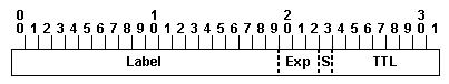
The S bit in the MPLS header is used for indicate the bottom level in the label stack.
A label is a short, four-byte, fixed-length, locally-significant identifier which is used to identify a Forwarding Equivalence Class (FEC). The label which is put on a particular packet represents the FEC to which that packet is assigned.
Label - Label Value (Unstructured), 20 bits
Exp - Experimental Use, 3 bits; currently used as a Class of Service (CoS) field.
S - Bottom of Stack, 1 bit; if this is set, it signifies that the current label is the last in the stack.
TTL - Time to Live, 8 bits
OSPF Not-So-Stubby Areas
NSSA:
- Behaves like stub area, except: may introduce external routes locally in the area
Totally NSSA no-summary:
- Behaves like totally stubby area, except: may introduce external routes locally in the area
- Cisco proprietary feature
OSPF Adjacencies on the Point-to-Point Link
Routing updates and topology information are passed only between adjacent routers.
OSPF adjacencies are formed on point-to-point links.
- Sends OSPF packets using multicast 224.0.0.5 (IPv4) or FF02::5 (IPv6)
Purpose of the BGP scan-time command:
To tune the BGP process which walks the BGP table and confirms the reachability of next hops.
It is responsible for BGP housekeeping by scanning both the BGP RIB and the IP RIB and cleaning and sorting things out.
BGP monitors the next hop of the installed routes to verify next-hop reachability and to select, install, and validate the BGP best path. By default, the BGP scanner polls the RIB for this information every 60 seconds. During the 60 second time period between scan cycles, IGP instabilities or other network failures can cause temporarily black holes and routing loops.
NOTE: With Cisco IOS the default timer is 60 seconds for the IPv4 address family and 15 seconds for the VPNv4 address family in order to optimize the VPNs routing table convergence.
This timer can be controlled via the following command:
Router(config-router)# bgp scan-time
When using the show bgp ipv6 unicast summary command to verify the IPv6
BGP session status with the IPv6 BGP peers, you noticed the "St/PfxRcd"
status for one of the IPv6 BGP peers is in the "Active" state. The "Active" state indicate the router is in the process of establishing the IPv6 BGP session with the IPv6 BGP peer.
BGP configuration groupings are supported on Cisco IOS XR Software: af-group, session-group, and neighbor-group.
Commands relating to a peer group found in Cisco IOS Release 12.2 have been removed from Cisco IOS XR software. Instead, the af-group, session-group, and neighbor-group configuration commands are added to support the neighbor in Cisco IOS XR software:
- The af-group command is used to group address family-specific neighbor commands within an IPv4 or IPv6 address family. Neighbors that have the same address family configuration are able to use the address family group name for their address family-specific configuration. A neighbor inherits the configuration from an address family group by way of the use command. If a neighbor is configured to use an address family group, the neighbor will (by default) inherit the entire configuration from the address family group. However, a neighbor will not inherit all of the configuration from the address family group if items are explicitly configured for the neighbor.
- The session-group command allows you to create a session group from which neighbors can inherit address family-independent configuration. A neighbor inherits the configuration from a session group by way of the use command. If a neighbor is configured to use a session group, the neighbor (by default) inherits the session group's entire configuration. A neighbor does not inherit all the configuration from a session group if a configuration is done directly on that neighbor.
- The neighbor-group command helps you apply the same configuration to one or more neighbors. Neighbor groups can include session groups and address family groups. This additional flexibility can create a complete configuration for a neighbor. Once a neighbor group is configured, each neighbor can inherit the configuration through the use command. If a neighbor is configured to use a neighbor group, the neighbor (by default) inherits the neighbor group's entire BGP configuration.
- However, a neighbor will not inherit all of the configuration from the neighbor group if items are explicitly configured for the neighbor. In addition, some part of the neighbor group's configuration could be hidden if a session group or address family group was also being used.
ip as-path access-list permit^$ is AS path access list used by a multihomed customer to only
announce their own address space to their service providers to prevent
the multihomed customer from becoming a transit AS.
http://blog.ine.com/tag/as-path
^ = Start of string
$ = End of string
[] = Range of characters
- = Used to specify range ( i.e. [0-9] )
( ) = Logical grouping
. = Any single character
* = Zero or more instances
+ = One or more instance
? = Zero or one instance
_ = Comma, open or close brace, open or close parentheses, start or end of string, or space
Some commonly used regular expressions include:
.* = Anything ^$ = Locally originated routes
^100_ = Learned from AS 100
_100$ = Originated in AS 100
_100_ = Any instance of AS 100
^[0-9]+$ = Directly connected ASes
When troubleshooting OSPF neighbor errors, verification steps should be considered:
Verify if neighboring OSPF interfaces are configured in the same area.
Verify if neighboring OSPF interfaces are configured with the same hello and dead intervals.
Verify if neighboring OSPF interfaces are configured with the same area type.
Verify if neighboring OSPF interfaces are configured with the same mtu.
Verify if neighboring OSPF interfaces are configured ip mtu command.
Recursive lookup in BGP:
The router looks up the BGP route and
the BGP next hop to reach a destination in the remote AS. Then the
router looks up the route to reach the BGP next hop using the IGP.
A few different approaches are available to deal with iBGP and synchronization. We may turn on the synchronization option on our routers and wait for the IGP to have a route for the destination before it's advertised to peers. Another option is to simply use a full mesh, so that iBGP convergence isn't an issue. Clearly that isn't going to happen when a network's core needs to scale: it will implement something like reflectors that cause iBGP's full mesh to be broken.
The real alternative, if you don't enable synchronization, is to use route recursion. A recursive route lookup uses the BGP next-hop attribute to actually make a different route lookup. The IGP can use the destination network instead of the AS-path to determine where it gets sent. Even if the iBGP hasn't converged, the routers will still know how to get to that network, since it will exist in the router it was advertised from, who will know the next-hop.
AS 23456 is reserved AS number or range of numbers is used for backward
compatibility between old BGP peers using 16-bit AS number and new BGP
New Reserved AS#
AS_TRANS = AS #23456
2-byte placeholder for a 4-byte AS number
Used for backward compatibility between OLD and NEW BGP speakers
Communities BGP attribute is a set of generic tags that can be used to signal various routing policies between BGP routers.
http://www.cisco.com/en/US/tech/tk365/technologies_configuration_example09186a00801475b2.shtml
An enterprise network that is connected to two or more different
service providers with two or more links per service provider and using
BGP to exchange routing updates with the service providers is a characteristic of dual-multihomed
connectivity between an enterprise network and the service provider
network or networks.
Ways to advertise networks into BGP:
Using the network router BGP command.
Using route redistribution into BGP.
When configuring BGP on Cisco IOS XR Software, no address-family is enabled by default.
An address family must be explicitly configured in the router configuration mode for the address family to be active in BGP. Similarly, an address family must be configured under the neighbor for the BGP session to be established for that address family. An address family must be configured in router configuration mode before it can be configured under a neighbor.
Characteristics of the multihomed customers to service providers connection option:
The traffic load can be shared for different destination networks between service providers.
The routing methodology must be capable of reacting to dynamic changes. BGP is used to achieve this flexibility.
Referring to the partial Cisco IOS-XR BGP configuration exhibit.
When trying to commit this configuration, the following error is displayed:
%
Failed to commit one or more configuration items during a pseudo-atomic
operation. All changes made have been reverted. Please issue 'show
configuration failed' from this session to view the errors.
The configuration is missing the address-family ipv4 unicast and address-family ipv6 unicast commands under router bgp 65111 is wrong with the configuration.
The BGP Prefix-Based outbound route filtering feature:
IP multicast routes are not supported.
Outbound route filtering is configured only on a per-address family basis.
Restrictions for BGP Prefix-Based Outbound Route Filtering
- The BGP Prefix-Based Outbound Route Filtering feature does not support IP multicast routes.
- IP addresses that are used for outbound route filtering must be defined in an IP prefix-list. BGP distribute lists and IP access lists are not supported.
- Outbound route filtering is configured on only a per-address family basis and cannot be configured under the general session or BGP routing process (Router(config-router)#).
- Outbound route filtering is configured for only external peering sessions.
Refer to the Cisco IOS-XR route policy exhibit.
route-policy setcomm
if community matches-any (11:11, 44:44) then
set community (55:55) additive
elseif community matches-any (22:22) then
set community (77:77) additive
endif
If a route has both the 11:11 and 22:22 communities (or 44:44 and 22:22), the router adds the 55:55 community only.
Refer to the BGP and route map configurations exhibit.
router bgp 65001
neighbor 10.1.1.2 remote-as 65023
neighbor 10.1.1.2 route-map setas out
!
route-map setas permit 10
match ip address test1
set as-path prepend 65111 65112
!
route-map setas permit 20
match ip address test2
set as-path prepend 65202 65203 65204
!
!end of the route-map configuration
When
the "setas" route map is applied to the 10.1.1.2 neighbor, the 10.1.1.2
neighbor is not able to receive all the required BGP routes from this
router. The problem could be the route map is missing the route-map setas permit 30 statement.
In Cisco IOS and Cisco IOS XE Software images, when redistributing
routes from other routing protocols into OSPF, a common reason
why some of the routes might not be redistributed into OSPF is the subnets option in the redistribute command is missing.
on the Cisco IOS XR route policy configuration, when redistributing
OSPF routes into IS-IS, the tag value identifies a route or set of routes does the "tag" value
correspond.
When configuring Cisco IOS route maps, continue command allows the route
map processing to jump to another statement instead of exiting.
Match Operations With Continue Clauses
If a match clause does not exist in the route-map entry but a continue clause does, the continue clause will be automatically executed and go to the specified route-map entry.
If a match clause exists in a route-map entry, the continue clause is executed only when a successful match occurs.
When a successful match occurs and a continue clause exists, the route map executes the set clauses and then goes to the specified route-map entry.
If the next route map contains a continue clause, the route map will execute the continue clause if a successful match occurs.
If a continue clause does not exist in the next route map, the route map will be evaluated normally.
If a continue clause exists in the next route map but a match does not occur, the route map will not continue and will "fall through" to the next sequence number if one exists.
Set Operations With Continue Clauses
Set clauses are saved during the match clause evaluation process and executed after the route-map evaluation is completed. The set clauses are evaluated and executed in the order in which they were configured. Set clauses are only executed after a successful match occurs, unless the route map does not contain a match clause. The continue statement proceeds to the specified route-map entry only after configured set actions are performed. If a set action occurs in the first route map and then the same set action occurs again, with a different value, in a subsequent route map entry, the last set action may override any previous set actions that were configured with the same set command unless the set command permits more than one value. For example, the set as-path prepend command permits more than one autonomous system number to be configured.
Refer to the Cisco IOS route map configuration exhibit.
route-map test permit 10
match ip address prefix-list PL1 PL2
match as-path APACL1
set local-preference 200
set metric 1000
!
route-map test permit 100
The match prefix-list condition is a logical OR: match prefix list PL1 OR PL2.
The local preference AND the metric will be set to 100 IF the route
matches the PL1 OR PL2 prefix list AND the route must also match the
APACL1 AS path access list.
http://www.routeralley.com/ra/docs/route_maps.pdf
when match criteria is contained within a single line, a logical OR is applied.
Refer to the route policies exhibit.
route-policy one
end-policy
!
route-policy two
pass
end-policy
!
route-policy three
drop
end-policy
!
route-policy four
set weight 100
end-policy
!
route-policy five
pass
drop
pass
end-policy
route-policy one will cause the routes to be dropped.
route-policy two will cause the routes to be passed.
route-policy three will cause the routes to be dropped.
route-policy four will cause the routes to be passed.
route-policy five will cause the routes to be dropped.
When using the Cisco IOS XR route policy language to define a logical
if-then-else condition, NOT is logical operator has the highest
Boolean Operator Precedence
Boolean expressions are evaluated in order of operator precedence, from left to right. The highest precedence operator is not, followed by and, and then or. The following expression:
med eq 10 and not destination in (10.1.3.0/24) or community matches-any ([10..25]:35)
if fully parenthesized to display the order of evaluation would look like this:
(med eq 10 and (not destination in (10.1.3.0/24))) or community matches-any ([10..25]:35)
The inner not applies only to the destination test; the and combines the result of the not expression with the Multi Exit Discriminator (MED) test; and the or combines that result with the community test. If the order of operations are rearranged:
not med eq 10 and destination in (10.1.3.0/24) or community matches-any ([10..25]:35)
then the expression, fully parenthesized, would look like the following:
((not med eq 10) and destination in (10.1.3.0/24)) or community matches-any ([10..25]:35)
When configuring Cisco IOS XR route policy nesting, apply command is used within a route policy to call another route policy.
In the following example, the policy CustomerIn applies the route-policy SetLocalPref to conditionally set the local preference on a route. The parameters 20, 30, 40, and 50 are passed to the parameterized policy SetLocalPref, where the local preference is set to:
- 20, if the community 217:20 is present in the route
- 30, if the community 217:30 is present in the route
- 40, if the community 217:40 is present in the route
- 50, if the community 217:50 is present in the route
RP/0/RP0/CPU0:router(config)# route-policy SetLocalPref ($lp0, $lp1, $lp2, $lp3, $lp4)
RP/0/RP0/CPU0:router(config-rpl)# if community matches-any ($lp0:$lp1) then
RP/0/RP0/CPU0:router(config-rpl-elseif)# set local-preference $lp1
RP/0/RP0/CPU0:router(config-rpl-elseif)# elseif community matches-any ($lp0:$lp2) then
RP/0/RP0/CPU0:router(config-rpl-elseif)# set local-preference $lp2
RP/0/RP0/CPU0:router(config-rpl-elseif)# elseif community matches-any ($lp0:$lp3) then
RP/0/RP0/CPU0:router(config-rpl-elseif)# set local-preference $lp3
RP/0/RP0/CPU0:router(config-rpl-elseif)# elseif community matches-any ($lp0:$lp4) then
RP/0/RP0/CPU0:router(config-rpl-elseif)# set local-preference $lp4
RP/0/RP0/CPU0:router(config-rpl-elseif)# endif
RP/0/RP0/CPU0:router(config-rpl)# end-policy
route-policy SetLP
if med eq 10 then
set local-preference 200
endif
if local-preference eq 100 then
set weight 100
endif
if local-preference eq 200 then
set weight 200
endif
end-policy
If the original incoming routing update has a MED of 10 and a local preference of 100, the local preference will be set to 200, the MED will be set to 10, and the weight will be set to 100.
The IS-IS routing protocol allows for a two-level hierarchy of routing information. There can be multiple Level 1 areas interconnected by a contiguous Level 2 backbone. A router can belong to Level 1, Level 2, or both. The Level 1 link-state database contains information about that area only. The Level 2 link-state database contains information about that level as well as each of the Level 1 areas. An L1/L2 router contains both Level 1 and Level 2 databases. It advertises information about the L1 area to which it belongs into L2. Each L1 area is essentially a stub area. Packets destined for an address that is outside of the L1 area are routed to the closest L1/L2 router to be forwarded on to the destination area. Routing to the closest L1/L2 router can lead to sub-optimal routing when the shortest path to the destination is through a different L1/L2 router. Route leaking helps reduce sub-optimal routing by providing a mechanism for leaking, or redistributing, L2 information into L1 areas. By having more detail about interarea routes, an L1 router is able to make a better choice with regard to which L1/L2 router to forward the packet.
Refer to the exhibit.
Configuration options can be used to optimize the IS-IS network scenario:
Change the Gi0/0 interface IS-IS circuit type on R1 and R2 to Level 2 only.
Change the Gi0/1 interface IS-IS circuit type on R1 and R2 to Level 1.
Implement OSPF Routing
Task 1: Enable OSPF on the Routers
Step 1 The IP addresses configured on the CE and PE routers:
CE1 (Cisco IOS):
interface Loopback0
ip address 10.1.10.1 255.255.255.255
!
interface GigabitEthernet0/0
ip address 192.168.101.11 255.255.255.0
no shutdown
Step 9 The OSPFv3 enabled on the CE and PE routers:
CE1 (Cisco IOS):
interface Loopback0
ipv6 ospf 1 area 11
!
interface GigabitEthernet0/0
ipv6 ospf 1 area 11
PE1 (Cisco IOS XR):
router ospfv3 1
area 0
interface GigabitEthernet0/0/0/1
!
interface GigabitEthernet0/0/0/2
!
interface GigabitEthernet0/0/0/3
!
area 1
interface Loopback0
!
area 11
interface GigabitEthernet0/0/0/0
!
commit
CE2 (Cisco IOS):
interface Loopback0
ipv6 ospf 1 area 12
!
interface GigabitEthernet0/0
ipv6 ospf 1 area 12
PE2 (Cisco IOS XE):
interface Loopback0
ipv6 ospf 1 area 2
!
interface GigabitEthernet0/0/0
ipv6 ospf 1 area 12
!
interface GigabitEthernet0/0/1
ipv6 ospf 1 area 0
!
interface GigabitEthernet0/0/2
ipv6 ospf 1 area 0
!
interface GigabitEthernet0/0/3
ipv6 ospf 1 area 0
Verification:
CE1# show ip protocols
CE1# show ip ospf neighbor
CE1# show ip ospf database
CE1# show ip route ospf
CE1# show ipv6 protocols
CE1# show ipv6 ospf neighbor
CE1# show ipv6 ospf database
CE1# show ipv6 route ospf
PE1# show protocols
PE1# show ospf neighbor
PE1# show ospf database
PE1# show route ospf
PE1# show protocols ipv6
PE1# show ospfv3 neighbor
PE1# show ospfv3 database
PE1# show route ipv6 ospf
A ping from the CE1 router to the CE2 router should be successful both ipv4 and ipv6.
Task 2: Influence OSPF DR and BDR Election
Step 1 Configuration entered on the CE1 and CE2 router:
interface GigabitEthernet0/0
ip ospf priority 0; Priority number zero (0) never becomes DR neither BDR. And it take effect immediately.
Step 2 Configuration entered on the PE1 router:
router ospf 1
area 0
interface GigabitEthernet0/0/0/2
priority 2; default = 1, larger priority number wins, it will change when the current DR will go down.
interface GigabitEthernet0/0/0/3
priority 2
!
commit
Configuration entered on the PE2 router:
interface GigabitEthernet0/0/2
ip ospf priority 2
interface GigabitEthernet0/0/3
ip ospf priority 2
Verification:
PE1# show ospf interface GigabitEthernet x/x/x/x | include State
Refer to the network diagram in the exhibit.
Assuming
the IBGP session within AS 64500 was established using the loopback 0
interface between the two routers, by default, 192.168.101.11 is the next hop
of the routes from AS 64501 when the routes appear on the router
running IBGP only in AS 64500.
Global variables that can be referenced by any route policy is defined by using the Cisco IOS XR policy-global configuration command
Global Configuration Mode
Prompt: (config)
Enter global configuration mode from executive (EXEC) mode by using the configure command. Global configuration commands generally apply to the whole system rather than just one protocol or interface. You can enter all other configuration submodes listed in this section from global configuration mode.
Enter global parameter configuration mode by using the policy-global command in global configuration mode. In global parameter configuration mode, you can create or modify a global policy by entering successive commands and then terminating the configuration by entering the end-global command.
Use an AS-path access-list to filter the BGP updates to the ISPs can prevent multihomed customers with connections to two service providers from acting as a transit AS.
Refer to the Cisco IOS XR route policy exhibit.
route-policy new
if community matches-any test then
set local-preference 10
elseif community matches-every foo then
set local-preference 20
else
pass
endif
end-policy
"test" and "foo" are references to the community sets.
All non-matching routes will be permitted.
Task 3: Influence OSPF Route Selection by Changing OSPF Link Cost
Step 1 Verify the route that is selected for prefixes. The OSPF selects a direct link and does not use backbone routers:
PE1#show route 10.2.1.1
PE1#show route 10.2.10.1
Step 2
Configuration entered on the PE1 router:
router ospf 1
area 0
interface GigabitEthernet0/0/0/3
cost 3; Default Interface Cost= Reference bandwidth/interface bandwidth
!
commit
Configuration entered on the PE2 router:
interface GigabitEthernet0/0/2
ip ospf cost 3
Step 3 Change OSPF link cost between PE routers.
Configuration entered on the PE1 router:
router ospf 1
area 0
interface GigabitEthernet0/0/0/1
cost 10
!
commit
Configuration entered on the PE2 router:
interface GigabitEthernet0/0/1
ip ospf cost 10
Verification:
PE1# show route 10.2.1.1
PE1# show route 10.2.10.1
PE1# traceroute 10.2.1.1
PE2# show ip route 10.1.1.1
PE2# show ip route 10.1.10.1
PE2# traceroute 10.1.1.1
Task 4: Configure OSPF Authentication
Step 1 The OSPF MD5 authentication is enabled on the CE and PE routers:
CE1 and CE2 (Cisco IOS):
interface GigabitEthernet0/0
ip ospf authentication message-digest
ip ospf message-digest-key 1 md5 cisco
PE2 (Cisco IOS XE):
interface GigabitEthernet0/0/0
ip ospf authentication message-digest
ip ospf message-digest-key 1 md5 cisco
Verification:
PE1# show ospf neighbor 10.10.10.10 | include State
PE1# show ospf interface GigabitEthernet0/0/0/0
PE2# show ip ospf neighbor 20.20.20.20 | include State
PE2# show ip ospf interface GigabitEthernet0/0/0
Task 5: Configure OSPF Virtual Links
Step 1 Enable new Loopback interface on the CE router:
CE1 (Cisco IOS):
interface Loopback11
ip address 11.0.0.1 255.255.255.0
CE2 (Cisco IOS):
interface Loopback12
ip address 12.0.0.1 255.255.255.0
Step 3 On the CE router, examine the IP routing table, and should see intra-area and interarea OSPF routes. There are no external OSPF routes in the routing table; instead, should see a default route:
CE1# show ip route
Step 4 Configure OSPF totally stubby area on the PE router:
Step 5 On the CE router, examine the IP routing table, and should see only intra-area OSPF routes. There are no interarea or external OSPF routes in the routing table; instead, should see a default route:
CE1# show ip route
Step 6 Adjust the OSPF cost of the default route on the PE router:
Step 7 Examine the OSPF database on the CE router. There should be a summary LSA that includes a default route with metric 10:
CE1# show ip ospf database summary 0.0.0.0
Step 8 Examine the OSPF default route metric on the CE router. The metric of the default route is 11:
CE1# show ip route 0.0.0.0
Step 9 Because the OSPF area between the CE and PE routers is configured as stub, there is no IP reachability to the Loopback11 or Loopback12. The stub area does not support an ASBR router inside the area. To get IP reachability, change the stub area into a totally NSSA. A totally NSSA allows an ASBR router inside the area:
CE1 (Cisco IOS):
router ospf 1
no area 11 stub
area 11 nssa
PE1 (Cisco IOS XR):
router ospf 1
area 11
no stub
nssa no-summary
!
commit
CE2 (Cisco IOS):
router ospf 1
no area 12 stub
area 12 nssa
PE2 (Cisco IOS XE):
router ospf 1
no area 12 stub
area 12 nssa no-summary
Verification:
On the PE router, verify the OSPF database. There should be type 7 LSA, originated by the CE router. Type 7 LSA describes the CE Loopback11 or Loopback12 network.
PE1# show ospf database nssa-external
The PE router translates type 7 LSA into type 5 LSA. On the PE, verify the OSPF database. There should be type 5 LSA originated by the PE router. Type 5 LSA describes the CE Loopback11 or Loopback12 network.
PE1# show ospf database external 11.0.0.0
CE1# ping 12.0.0.1 (Lo12 IP address from CE2 router)
สำหรับ OSPF แล้ว จะมีวิธีการ update route หรือการประกาศ route ผ่านทาง OSPF packet ที่มีชื่อว่า LSA โดย LSA จะมีด้วยกันหลายชนิด หรือหลาย type ซึ่งจะมีตั้งแต่ LSA type 1 ถึง SLA type 11
1 Router: Defines the state and cost of the link to the neighbor and IP prefix associated with the point-to-point link.
2 Network: Defines the number of routers attached to the segment. It gives information about the subnet mask on that segment.
3 Summary network: Describes the destination outside an area but within the OSPF domain. The summary for one area is flooded into other areas, and vice versa.
4 Summary ASBR: Describes the information about the ASBR. In a single area, there will be no summary Type 4 LSA.
5 External: Defines routes to destination external to OSPF domain. Every subnet is represented by a single external LSA.
6 Group membership
7 NSSA: Defines routes to an external destination, but in a separate LSA format known as Type 7.
8 Unused, 9 - 11 Opaque
LSA type ที่จะพบแน่ๆ ในชีวิตประจำวันกับ network ที่เป็น OSPF Domain จะมีดังนี้คือ LSA type 1, 2, 3, 4, 5 และ 7
ซึ่งถ้าแปลเป็นไทยก็คือ ไม่ใช่ Stub Area ซะทีเดียว โดย NSSA จะคล้ายๆ กับ
Stub Area แต่จะสามารถมี ASBR ภายใน NSSA Area ได้ โดย ASBR ที่อยู่ใน NSSA
Area จะรับ external route เข้ามาจากการ redistribute external route
จากภายนอก OSPF Domain เข้ามาใน NSSA Area และ ASBR จะทำการแปลง External
route ให้กลายเป็น route ที่อยู่ใน LSA type 7 (เพราะ NSSA Area และ Stub
Area ห้ามมี External route (LSA type 5) นั่นเอง) และจาก NSSA ที่มีหลักการคล้ายๆ กับ Stub Area คือห้ามมี LSA Type 5 ดังนั้น ABR ของ NSSA Area เมื่อรับ route จาก Backbone Area (Area 0) เข้ามา จะรับแค่ route ใน LSA type 3 เท่านั้น ส่วน route ที่อยู่ใน LSA type 5 ที่เข้ามาจะถูกแปลงเป็น default route ด้วยการ configure อย่าง manual บน ABR แล้ว ABR จึงประกาศ Default route นี้เข้าไปใน NSSA Area ของตนเอง
ตัวอย่างการ configure ให้ ABR ของ NSSA ประกาศ default route เข้าไปใน NSSA Area
router ospf 10
area 1 nssa default-information-originate
เมื่อ Area 1 = NSSA Area และ ABR จะประกาศ default route เข้าไปใน NSSA Area ด้วย command "default-information-originate"
Note: LSA type 7 เมื่อถูกประกาศออกไปนอก NSSA Area (ประกาศเข้าไปใน Backbone Area (Area 0)) ABR ของ NSSA Area จะทำการแปลง LSA type 7 นี้ให้กลายเป็น LSA type 5 ก่อน แล้วจึงประกาศเข้าไปใน Backbone Area เพราะ area อื่นๆ รู้จักแค่ LSA type 3 และ LSA type 5 ไม่รู้จัก LSA type 7
(LSA type 5 และ LSA type 7 เป็น LSA ที่บรรทุก external route ทั้งคู่ แต่เนื่องด้วย NSSA เป็น area ที่ห้ามมี LSA type 5 มันจึงเล่นแร่แปรธาตุหนีมาใช้เป็น LSA type 7 นั่นเอง)
Totally NSSA ก็คือ NSSA Area ที่ไม่รับทั้ง route ที่อยู่ใน LSA type 3 และ LSA type 5 นั่นเอง ดังนั้น ABR ของ Totally NSSA Area จะเป็นผู้แปลงทั้ง route ที่อยู่ทั้งใน LSA type 3 และ LSA type 5 ให้กลายเป็น default route แล้วประกาศเข้าไปใน Totally NSSA ให้อย่างอัตโนมัติ ไม่ต้อง manual configure เหมือนอย่างการประกาศ default route NSSA ธรรมดา
เปรียบเทียบ Stub area กับ NSSA area
ความเหมือนกันของ Stub area กับ NSSA area
- Area ทั้งสองแบบ เป็น area ที่รับมาแค่ LSA type 3 จาก Backbone area เท่านั้น แต่จะไม่รับ LSA type 5 จาก Backbone area โดย ABR จะเป็นผู้คัดกรองให้
- เหมาะกับ area ที่มี router รุ่นเล็กๆ หรือ router ที่มี performance ต่ำๆ
ความแตกต่างกันของ Stub area กับ NSSA area
- Stub area ห้ามมี ASBR อยู่ภายใน area แต่ NSSA area สามารถมี ASBR อยู่ใน area ได้
- Stub area จะไม่มี LSA type 7 แต่ NSSA area จะมี LSA type 7
- ABR ของ Stub area จะสร้าง หรือ generate default route แล้วประกาศเข้าสู่ area ของตนเองอย่างอัตโนมัติ แต่ ABR ของ NSSA area จะไม่สร้าง หรือ ไม่ generate default route อย่างอัตโนมัติเหมือนอย่าง Stub area แต่ network administrator จะต้องเป็นผู้ configure default route เอง อย่าง manual
เปรียบเทียบ Totally Stubby area กับ Totally NSSA area
ความเหมือนกันของ Totally Stubby area กับ Totally NSSA area
- Area ทั้งสองแบบ เป็น area ที่ไม่รับทั้ง LSA type 3 และ LSA type 5 จาก Backbone area โดย ABR จะเป็นผู้คัดกรองให้
- เหมาะกับ area ที่มี router รุ่นเล็กๆ หรือ router ที่มี performance ต่ำๆ
ความแตกต่างกันของ Totally Stubby area กับ Totally NSSA area
- Totally Stubby area ห้ามมี ASBR อยู่ภายใน area แต่ Totally NSSA area สามารถมี ASBR อยู่ใน area ได้
- Totally Stubby area จะไม่มี LSA type 7 แต่ Totally NSSA area จะมี LSA type 7
จะใข้ Stub area, Totally Stubby, NSSA area และ Totally NSSA area นี้เมื่อไหร่?
router ospf 100
bfd minimum-interval 2
bfd multiplier 20
area 0
interface GigabitEthernet0/3/0/1
interface GigabitEthernet0/3/0/2
end
Cisco IOS XR configuration is missing to
complete the configuration task of enabling BFD with only the OSPF peer
over the gi0/3/0/1 interface in area 0 by bfd fast-detect also needs to be enabled for the OSPF interface under area 0 interface gi0/3/0/1.
RP/0/RSP0/CPU01(config-ospf-ar-if)#bfd fast-detect
bfd fast-detect
To enable Bidirectional Forwarding Detection (BFD) to detect failures in the path between adjacent forwarding engines, use the bfd fast-detect command in the appropriate configuration mode. To return the software to the default state in which BFD is not enabled, use the no form of this command.
bfd fast-detect [disable | ipv4]
no bfd fast-detect
NSF is high-availability routing feature requires the neighbor router to support the graceful restart capability.
On Cisco IOS XR software, NSF minimizes the amount of time a network is unavailable to its users following a route processor (RP) failover. The main objective of NSF is to continue forwarding IP packets and perform a graceful restart following an RP failover.
When a router restarts, all routing peers of that device usually detect that the device went down and then came back up. This transition results in what is called a routing flap, which could spread across multiple routing domains. Routing flaps caused by routing restarts create routing instabilities, which are detrimental to the overall network performance. NSF helps to suppress routing flaps in NSF-aware devices, thus reducing network instability.
NSF allows for the forwarding of data packets to continue along known routes while the routing protocol information is being restored following an RP failover. When the NSF feature is configured, peer networking devices do not experience routing flaps. Data traffic is forwarded through intelligent line cards while the standby RP assumes control from the failed active RP during a failover. The ability of line cards to remain up through a failover and to be kept current with the Forwarding Information Base (FIB) on the active RP is key to NSF operation.
When the Cisco IOS XR router running IS-IS routing performs an RP failover, the router must perform two tasks to resynchronize its link-state database with its IS-IS neighbors. First, it must relearn the available IS-IS neighbors on the network without causing a reset of the neighbor relationship. Second, it must reacquire the contents of the link-state database for the network.
The IS-IS NSF feature offers two options when configuring NSF:
- IETF NSF
- Cisco NSF
If neighbor routers on a network segment are NSF aware, meaning that neighbor routers are running a software version that supports the IETF Internet draft for router restartability, they assist an IETF NSF router that is restarting. With IETF NSF, neighbor routers provide adjacency and link-state information to help rebuild the routing information following a failover.
Refer to the Cisco IOS show command output shown in the exhibit.
R1# show ip bgp 10.2.10.1
BGP routing table entry for 10.2.10.1/32, version 32
Paths: (2 available, best #2, table default)
Advertised to update-groups:
2
64500 64500 64502
192.168.103.30 from 192.168.103.30 (10.3.1.1)
Origin IGP, localpref 100, weight 100, valid, external
64500 64500 64502
192.168.134.40 (metric 11) from 192.168.134.40 (10.4.1.1)
Origin IGP, localpref 100, weight 200, valid, external, best
R1# show ip bgp
BGP table version is 89, local router ID is 11.0.0.1
Status codes: s suppressed, d damped, h history, * valid, > best, i - internal,
r RIB-failure, S Stale
Origin codes: i - IGP, e - EGP, ? - incomplete
Network Next Hop Metric LocPrf Weight Path
*> 10.2.10.1/32 192.168.201.20 200 64500 64500 64500 64500 64502 i
192.168.101.10 100 64500 64500 64502 i
The best path to 10.2.10.1/32 was chosen because of the weight.
Implement Integrated IS-IS Routing
Task 1: Enable Integrated IS-IS on the Routers
Step 1:
CE1# show ip interface brief | include GigabitEthernet0/0 | Loopback0
PE1# show ipv4 interface brief | include Up
Step 2 should be able to successfully test IP connectivity:
PE1# ping 192.168.101.11
PE1# ping 192.168.112.20
Step 3 Values used for IS-IS NET addressing, and interfaces used in IS-IS routing:
 1(config-ospf)#area 1 stub no-summary